Using the PWM Expansion
The PWM Expansion allows you to generate up to 16 different Pulse Width Modulated (PWM) signals to control anything from Servo Motors (servos), DC Motor speed, LED brightness, etc.
You can learn more about the technical specifications of the PWM expansion in our PWM Expansion hardware overview
Pulse Width Modulation
PWM is a technique to control power output from a circuit. Here’s an analogy to explain how this works. Let’s say you’re watering some delicate flowers in a garden. You have a very simple hose that can only be in either of the following states:
- off, or
- on at full blast, destroying your flowers! :(
PWM is the technique of rapidly turning the hose on and off so that the hose acts as a gentle sprinkler. For example, this can be used to vary the brightness of an LED, making it fade in and out instead of just blinking!
Servomotors use PWM signals in a different way. They analyze how long each pulse is (called the duty cycle) and use that to determine what angle they should rotate to.
Pulse Width Modulated signals can be described by duty cycle or periods.
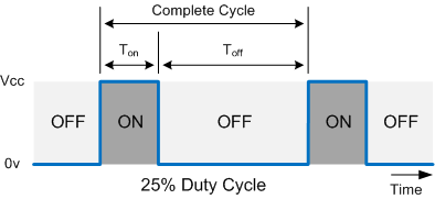
Duty Cycle
Indicates what percentage of the time a signal is on or high voltage. So a PWM signal with a 25% duty cycle will be high for 25% of the time, and low 75% of the time. The duty cycle can be calculated as follows:
\[DutyCycle = {\frac{T_{on}}{T_{CompleteCycle}}}\times100\%\]
Period and Frequency
The period is how much time it takes to complete one cycle. The command line tool uses milliseconds.
The Time On, Ton in the diagram above is the time the signal is high. This is also known as the pulse width.
Similarly, Time Off, or Toff is the time the signal is low.
The Complete Cycle time corresponds to the overall period of the PWM signal, and is equivalent to Time On + Time Off.
The frequency of the PWM signal is how many cycles the signal goes through per second, and is the reciprocal of period:
\[Frequency = {\frac{1}{Period}}\]
The unit of frequency is the Hertz (Hz). We will describe frequency numbers using Hz.
Using the Command Line
Make sure that your Omega has the latest firmware!
We’ve developed a tool called pwm-exp that should make generating PWM signals a breeze.
Also available are a C library and a Python module that allow you to develop your own programs to control the Servo Expansion. See the guides at the bottom of this article for more details.
Command Usage
For a print-out of the command’s usage, run it with only a -h argument:
pwm-exp -hInitialization
After every boot, the chip and oscillator on the Servo Expansion have to be initialized in order for the PWM signals to be generated correctly. The driver application will automatically detect if the oscillator is not running and will run the required sequence, so this command should only be run if you wish to initialize the oscillator but not generate any PWM signals.
To perform the initialization, run the following command:
pwm-exp -iThis can be run by itself or in conjunction with any commands below.
Setting the PWM based on Duty Cycle
The tool allows you to define the PWM signal to be generated by specifying which channel on the Expansion to use and the duty cycle:
pwm-exp [OPTIONS] <CHANNEL> <DUTY CYCLE PERCENTAGE>Examples:
Generating a signal on channel 0 with a 10% duty cycle:
pwm-exp 0 10Generating a signal using a frequency of 100Hz, on channel 1, with a 33.33% duty cycle:
pwm-exp -f 100 1 33.33Performing the initialization sequence and then generating a signal on channel 2 with a 95% duty cycle:
pwm-exp -i 2 95Note that the duty cycle must be between 0 and 100.
Setting the PWM based on Period
The PWM signal can also be generated by specifying the pulse width and total period in milliseconds:
pwm-exp -p <CHANNEL> <PULSE WIDTH> <TOTAL PERIOD>Some examples:
Generating a PWM signal based on period, on channel 3, that is high for 1ms, low for 19ms. This makes the overall period 20ms, corresponding to a 50Hz frequency:
pwm-exp -p 3 1 20Generating a PWM signal based on period, on channel 5, that is high for 1.65ms, for an overall period of 5.4ms (corresponds to 185.19 Hz)
pwm-exp -p 5 1.65 5.4Setting the PWM signal frequency
When setting the signal based on duty cycle, the frequency can also be adjusted in each command by using the -f option.
pwm-exp -f <FREQUENCY> <CHANNEL> <DUTY>An example:
Generating a signal that is 220Hz, on channel 5, with a 15% duty cycle:
pwm-exp -f 220 5 15The default frequency is 50 Hz. Most servos operate on this frequency.
If the desired frequency is different from the default, the frequency must be specified in each pwm-exp command. Otherwise the Expansion will reset to the default frequency.
Note that all channels run on the same frequency. It is not possible to generate PWM signals with different frequencies on the same Servo Expansion.
When setting the signal based on period, the frequency is dependent on the total period:
\[Frequency = {\frac{1}{Period}}\]
Selecting a Channel
The Servo Expansion has 16 channels, pwm-exp allows you to program each individually or all at once.
Programming each individually:
Seen in the examples above:
pwm-exp 12 97
pwm-exp -p 15 1.65 20
Programming all at once:
Instead of specifying a channel number, the keyword all will set all channels at once.
Setting all of the channels to a 50% duty cycle signal at the default 50Hz:
pwm-exp all 50Setting a signal at 123Hz on all channels to a 66% duty cycle:
pwm-exp -f 123 all 66Setting a signal based on period on all of the channels with a 5% duty cycle (1ms on, with a period of 20ms):
pwm-exp -p all 1 20Setting a Delay
It is also possible to create PWM signals where the pulse is delayed by some time.
The following image shows a 20% duty cycle signal with a 10% delay:

For the first 10% of the cycle, the signal is low. Then it will be high for the next 20% of the cycle, and low for the remaining 70% of the cycle.
Setting a delay with pwm-exp can only be done when setting the PWM signal using the duty cycle:
pwm-exp <CHANNEL> <DUTY CYCLE> <DELAY PERCENTAGE>Examples
Generating a signal like the one above, on all channels, with a 20% duty cycle, with a 10% delay:
pwm-exp all 20 10Generating a signal on channel 9, with 33% duty cycle, and a delay of 50%:
pwm-exp 9 33 50Disabling the Oscillator
The oscillator can be put into sleep mode, immediately disabling generation of all PWM signals. This might be useful in any application where you want to disable all connected servos or LEDs but keep the Omega powered on. For instance, we use the sleep mode to rest the servos on Oliver, our robotic arm, after he’s been powered on for too long.
To put the oscillator in sleep mode:
pwm-exp -sTo enable the oscillator again, there are a few methods:
Run the initialization sequence to enable the oscillator and generate no PWM signals:
pwm-exp -iGenerate a PWM signal on one or all channels, the software will detect the oscillator is in sleep mode and will run the initialization sequence:
pwm-exp <CHANNEL> <DUTY>or
pwm-exp -p <CHANNEL> <PULSE WIDTH> <TOTAL PERIOD>Using the Libraries
The C library and Python module will allow you to control the PWM Expansion with your own programs. See the guides below for more details: